
Installation diagram
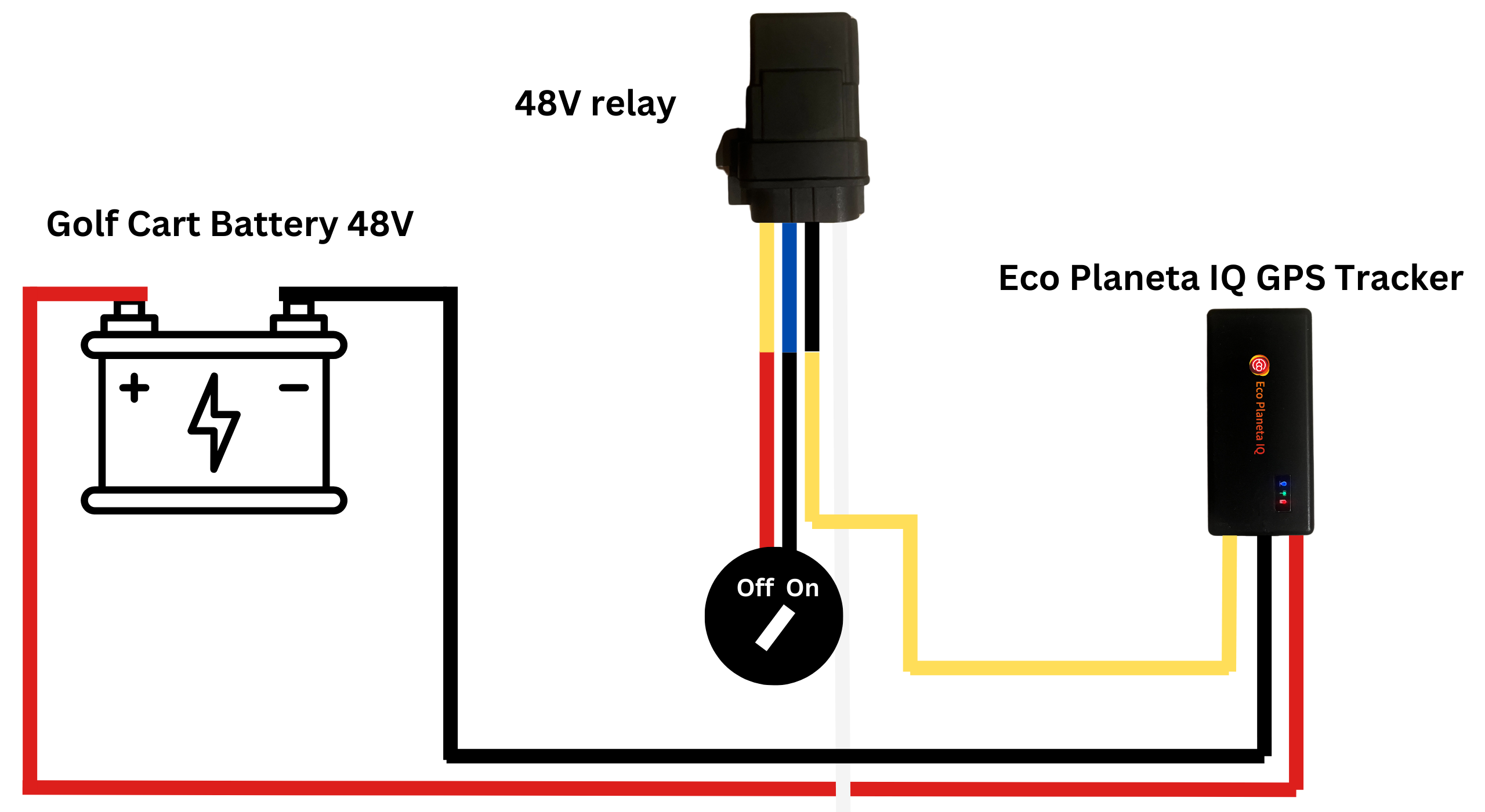
Please note that the yellow cable coming from the relay sometimes can be red.
We recommend to install both the relay and the gps tracker in the Controller Compartment. That way the devices are invisible and best protected for the elements.
Step 1: Prepare the Key Switch Interruption
Access the back of your Key Switch on the dash.
You will see two wires.
Disconnect both wires from the back of the key switch.
Step 2: Connect the "Switching" Side (The Bridge)
This part of the relay completes the ignition circuit that the key used to handle.
Connect Relay Pin 30 (red or yellow cable) to one of the wires you removed from the key switch.
Connect Relay Pin 87 (blue cable) to the other wire you removed from the key switch.
Note: On a 4-pin relay, these two are interchangeable. This creates the "break" in the ignition line that only the tracker can bridge.
Step 3: Connect the "Control" Side (The Trigger)
This is what "turns the key" electronically.
Connect Relay Pin 86 (white cable) to a Positive (+) power source. For safety, splice this into the tracker’s Red wire (on the side of the fuse closest to the tracker).
Connect Relay Pin 85 (black cable) to the Yellow wire from the Eco Planeta IQ Tracker.
Step 4: Power the Tracker
Connect the Tracker’s Red (fused) cable to the Battery Positive (+).
Connect the Tracker’s Black cable to the Battery Negative (-).
Hide the tracker and relay behind the dash panel or in the Controller Compartment for best protection against the elements.